Speed reducers are a very important part of mechanical power transmission systems. There are several different types available, each with certain features. Installing the wrong gear reducer into an application can be disastrous. The first step to choosing a gear reducer is to know what torque and speed are required as well as the most suitable motor to use. Next, if a gear reducer is needed, you select the proper type and ratio.
So what is a speed reducer? Usually, the benefits are that it can reduce speed and increase torque. The amount of speed reduction will depend on the type of motor used. For example, while one motor might not need a gear reducer to run at low speeds (as low as 1,000 rpm or so), another may need one to run at any speed.
For speed reducers, the gear ratio is calculated using the equation below. I is the gear ratio, and N1 is the speed of the motor and N2 is the output speed of the gear reducer.
I = N1 / N2
Speed reducers multiply the torque output of a motor. For this reason, a smaller, less expensive motor with a gear reducer may be the right decision for your application than a larger motor without one. To calculate the required gearbox ratio when torque multiplication is needed, use this equation: I is the gear ratio, T is torque, P1 is motor power, N1 is the motor speed and μ is efficiency.
I = T /9550 / P1 * N1 / μ
Another function of gear reducers is reducing the reflected load inertia to the motor by a factor of the square of the gear’s ratio. For most motion applications, the reduction of reflected inertia from motors is ideal. This is especially true for high-performance applications but is applicable for any motion application. Rather than only considering the gear’s ratio, you should also take into account the inertia of the load and the motor. To achieve perfect inertia matching, take the square root of the ratio of motor inertia to load inertia.
To calculate the speed and gear ratio required for your application, you must know the desired output speed and torque. Once you have these two pieces of information, you can use the following formula:
Output Speed (RPM) = Input Speed (RPM) / Gear Ratio
Where:
- Output Speed (RPM) is the desired speed of the output shaft
- Input Speed (RPM) is the speed of the input shaft, typically determined by the motor
- Gear Ratio is the ratio of the output speed to the input speed of the gearbox
For example, let’s say you have a load that requires an output speed of 100 RPM and an output torque of 100 lb-ft. Suppose your motor delivers an input speed of 1750 RPM and an input torque of 50 lb-ft. In that case, you can calculate the required gear ratio and output speed as follows:
Gear Ratio = Input Torque / Output Torque Gear Ratio = 50 / 100 Gear Ratio = 0.5
Output Speed (RPM) = Input Speed (RPM) / Gear Ratio Output Speed (RPM) = 1750 / 0.5 Output Speed (RPM) = 3500
Therefore, the required gear ratio is 0.5, and the output speed is 3500 RPM. It’s important to note that these calculations provide estimates and may vary based on factors such as motor efficiency and operating environment. It’s always recommended to consult with a gearmotor expert when selecting the right gearmotor for your application.
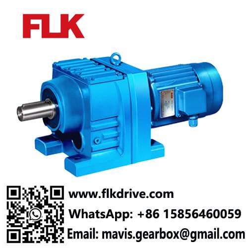
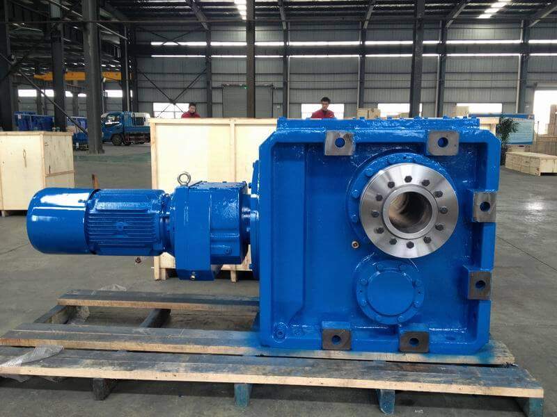
About FLK Drive Transmission
At FLK Drive Transmission, we work hand-in-hand with our customers to ensure that their industrial gearboxes, speed reducers, and accessories remain operational for years to come. Many of our products have been in high-speed and harsh environments for years. Clients make the switch to FLK Drive to experience that durability and decrease the amount of unscheduled downtime and maintenance in their facility. We ensure that every unit we design or repair leaves our factory quickly to keep your application up and running. Please call us at +86 15856460059 or contact us by email to receive a quote for your facility or information about our industrial gearboxes services. We will be glad to tell you more about our products and provide best service for you.