Introduction
Selecting a gearbox can be quite difficult. Customers have a variety of gearboxes to choose from that are capable of fulfilling diverse requirements. A wrong decision could result in the purchase of a more expensive gearbox. The power transmission industry may need a gearbox that will support overhung loads while the motion control or servo industry may need a gearbox that will handle dynamic motion.
One of the first problem areas for sizing arises from sizing to the motor versus sizing to the load. Sizing to the motor may be simpler and result in a gearbox that works, but it will result in the purchase of a larger gearbox than is needed. This gearbox will also be overqualified for the application. However, sizing to the load will ensure a gearbox fits the application and is more cost-effective as well as potentially a smaller footprint.
Common Aspects of Sizing Applications:
There are several aspects of gearbox sizing that apply to every situation. This section will detail those criteria and offer insight.
1. Service Factor
Before sizing an application, the customer should determine the service factor. Service factor can be generally defined as an application’s required value over the rated value of the unit. Service factor should be determined for conditions such as non-uniform load, hours of service, and elevated ambient temperature.
How would one interpret a service factor? A service factor of 1.0 means a unit has just enough capacity to handle the application. There is no tolerance for additional requirements, which could cause the gearbox to overheat or fail. For most industrial applications, a service factor of 1.4 is adequate. This service factor signifies that the gearbox can handle 1.4 times the application requirement. If the application requires 1,000 inch-pounds, the gearbox would be sized to handle 1,400 inch-pounds. Different factors will affect how much service factor should be used in a given application. The changes to the service factor depend on the manufacturer. Please examine the manufacturer’s specifications.
2. Ambient Temperature and Environment
Higher ambient temperatures increase internal pressure, which will require an increase in the service factor used. High or low temperatures can require different seal materials and lubrication viscosities.
The environment the gearbox will operate in is also an important consideration for sizing. Harsh environments can increase wear on the unit. Dusty or dirty environments often require special material to prevent corrosion or bacteria growth. Food or beverage plants require specific FDA compliant coatings and oil. Vacuum environments will require special grease and heat dissipation considerations since there will be no air for cooling. Failure to account for these environmental features can result in a gearbox that cannot support the application properly. All of these aspects must be considered when sizing a gearbox.
3. Shock Load or Type of Load
High shock or impact loads can cause increased wear on the gear teeth and shaft bearings. This wear could cause premature failure if not accounted for when sizing. These loads will require an increased service factor. Uniform loads are loads that remain constant during the application, while non-uniform loads change during the application. Non-uniform loads, even if small, will require a higher service factor than uniform loads. An example of a uniform load would be a conveyor with a consistent product amount riding on it. A non-uniform load would be any sort of intermittent cutting application. This intermittent cutting force causes a periodic increase in the torque on the gearbox, which is a non-uniform load.
4. Output Style or Mechanism
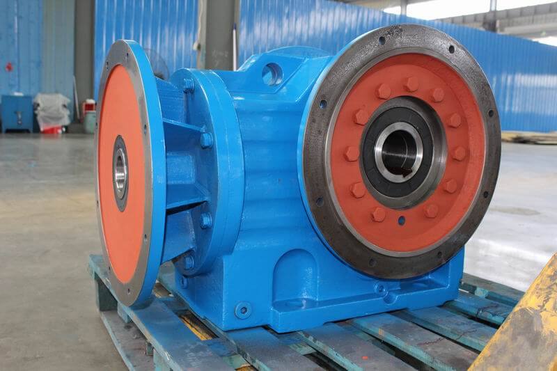
Output mechanisms include a sprocket, pulley, or toothed pinion, to name a few. Different output configurations, such as double output shaft or shaft mounted bushing, will decrease how much overhung load the unit is rated for. Different output mechanisms add different shaft loads that must be considered. Most mechanisms will cause high radial load, but things like helical gearing can also cause an axial load. These outputs could require different bearings to account for the increased radial or axial load.
5. Output Shaft or Hollow Bore Size
When sizing an application, the output shaft and bore size must meet customer requirements. These could include a stainless output on the unit, and whether it has a keyed or keyless shaft, a keyed or keyless hollow bore, or a flanged output combined with any of the previous. Getting the correct bore size on a unit may force the customer to purchase a larger gearbox or a different style of gearbox to fit their current shaft. In some instances, the customer can modify their shaft to use the most cost-effective unit while providing an optimal solution.
6. Housing Styles
It is also important when selecting a gearbox to consider how it will mount. A unit could have mounting feet, a flange on the output or just basic tapped holes on one or more sides. These housing styles could limit how a unit is mounted so having a variety of options could prevent custom frames or brackets from being needed. For example, having tapped holes on the bottom face of the unit would prevent the need for a special L-bracket to mount around the output.
Power Transmission:
Some elements that affect the sizing process are industry-specific. For the power transmission industry, output RPM, motor horsepower and frame size, and overhung load all impact the application calculations.
Output RPM
The customer must determine the ratio needed for the gearbox to operate, or provide input/output speed and operating hertz (Hz) for calculations. The standard is a 1750 input RPM at 60 Hz. Any changes will need to be specified when sizing as it will change the ratio calculation. Failure to account for changes will result in a gearbox that does not match the customer’s requirement.
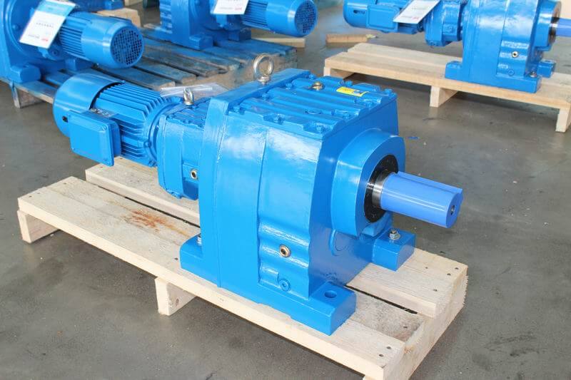
Motor HP and Frame Size
The gearbox size and input option must be determined before calculating the service factor. Once the gearbox is sized, use the required HP to compute the actual service factor. Large HP motors generate heat that can adversely affect the reducer’s mechanical ratings. This reduced rating, based on the increased heat, is known as the Thermal Capacity of a reducer and must be considered when using large motors.
General Shaft Load
The sizing must verify that the load will not damage the gearbox. The force, measured in pounds, that the output shaft is capable of sustaining is known as the Overhung Load rating. If the rating is less than the application, the speed reducer will be damaged.
Motion Control:
For the servo industry, input speed, inertia, dynamic torque motion, specific shaft loads, and motor shaft diameter affect the sizing process.
Input Speed
Input speed should not exceed the gearbox ratings or premature seal wear will occur due to increased pressure. Input speed can be accidentally increased if there is an output mechanism with a ratio that is not considered when sizing, which is another reason why specifying any output mechanisms is so important.
Inertia
An inertia mismatch of less than 10:1 is desired for fine controlling of the output. This is important to obtain the high accuracy needed for some applications. Reducer size and ratio are the main influences from the gearbox on inertia. Control engineers may request smaller mismatches or even specific amounts. Often a motor is chosen for its dynamic capabilities, not for its torque. It is common to use a motor with much more torque than needed for the application due to its increased rotor inertia. Some motor manufacturers even make motors specifically for high or low inertia ratings. This allows for better tuning of the application because of a lower inertia mismatch. When doing this, it is important to limit the output torque in the motor to prevent breaking the gearbox.
Dynamic Motion
Cyclic motion may require using a higher service factor than continuous motion. This is because constant starts and stops cause additional wear on the gear teeth and seals. Cyclic reversing, which is a constant back and forth motion between two points, requires an even higher service factor than cyclic or continuous.
Specific Shaft Loads
Radial, axial, and moment shaft loads must be checked against the unit’s ratings. Failure in doing this could result in a broken shaft or damage to the bearings or gear teeth. Generally, the same service factor is applied to these ratings to determine an appropriately strong gearbox. Additional bearing types can increase these ratings if the application needs them.
Motor Shaft Diameter or Length
The motor shaft must fit in the unit, and the shaft must be long enough for full engagement with the coupling. Without full engagement, input slippage could occur. While this will not affect the service factor needed, it is important to consider in order to avoid problems mounting the motor. Some manufacturers have a large input design allowing the reducer to accommodate the larger motor without increasing the unit size.
Conclusion:
To achieve the best gearbox solution, customers should size from the load. This will ensure they receive a cost-effective solution that fits the application. The service factor, environment, ambient temperatures, shock load, output style, and hours of service are all important aspects of sizing. The more information the customer provides, the more accurate the sizing process. This will ultimately yield a solution that matches the customer’s requirements! There are numerous sizing programs available that can help determine what gearbox is most appropriate for your application.