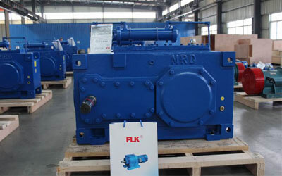
FLK Drive specializes in reducer manufacturing and explains how to repair reducers.
Start maintenance:
- Disassemble the machine and disassemble it step by step according to the structure of the equipment, and make detailed records to prevent mixed parts;
- Clean the reducer box and check for oil leaks;
- Inspect and measure the gears in the reducer, focusing on gear wear and meshing status, and record the inspection results;
- Measure the bearing clearance, check the wear, measure the shell, check the wear, and record the inspection results;
- Measure the input, output and intermediate shafts in the reducer, check the wear and tear, and record the inspection results;
- Summarize the above inspection results, summarize various dimensional deviations, and determine repair projects;
Maintenance operation process:
-
Disassemble the reducer:
(1) Descale and clean the outer surface of the disassembled reducer housing, and then clean it with kerosene;
(2) Drain the lubricating oil from the reducer;
(3) Use a special tool (puller) to remove the reducer pulley;
(4) Disassemble the output part of the reducer, remove the end cover fastening screws, use a jackscrew or a crowbar to separate the end cover, and then use a puller and a bearing press to remove the gears and bearings on the output shaft;
(5) Use the same method to remove the input shaft, gears and bearings of the input part;
(6) Use a bearing press or tap with a copper rod to remove the intermediate shaft, gears and bearings;
(7) Clean the above disassembled parts with kerosene;
(8) Check and measure the disassembled gears, bearings, shafts, end covers, shells, and bearing holes, and record the dimensions in detail;

-
Check the bearings:

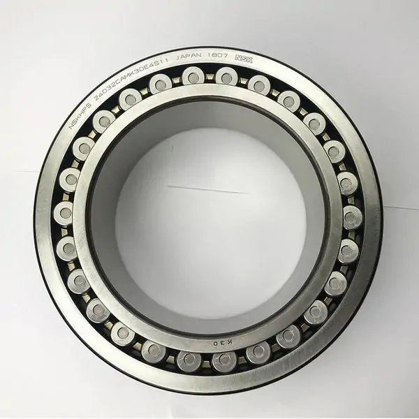
(1) Use a puller or bearing press to remove the bearing and clean it with kerosene;
(2) Check the bearing wear condition, shake the bearing, measure the shaft and radial clearance (0.02-0.2mm), turn to the bearing to listen to its sound, check the wear degree of the ball and groove surface, whether there are spots and annealing conditions, and severe cases. be replaced with a new one;
(3) Check and use a micrometer to measure the gap at the installation joint between the bearing and the shaft, and record the measurement results. The outer circle of the conventional fit size should be added 0.02-0.05mm. If it exceeds the range, it should be repaired;
(4) New bearings must be kept clean before assembly;
(5) For bearings that need to be filled with grease, the injection amount should be half of the bearing cavity;
(6) When assembling the bearing by press-fitting method, a special sleeve or rod must be used between the press tool and the bearing body. The same is used when installing by tapping to avoid damaging the bearing;
(7) The end faces of the inner and outer rings of the bearing should generally be close to the shaft shoulder and the inner hole shoulder. Generally, the conical and thrust bearings should not be larger than 0.05mm, and the others should not be larger than 0.1mm;
(8) After installation, the outer circle of the bearing and the inner hole of the housing should be in uniform contact, and the interference is generally between 0.02-0.05mm;
(9) When heating the bearing with oil or bearing heater, the temperature should not be higher than 120℃;
(10) For bearings with no installation direction, the end with the printed model number should face outward for easy viewing;
(11) Radially non-adjustable radial bearings are installed at both ends of the shaft, and when the axial displacement is limited by the glands at both ends, one end must be close and there must be axial clearance at the other end: the calculation formula is as follows:
C=0.000011×(80-t)L﹢0.15 (where L is the axis length and t is room temperature)
(12) The axial clearance of angular contact bearings is generally 0.04-0.1mm, and the axial clearance of cylindrical (tapered) roller bearings is generally 0.05-0.18mm;
-
Repair the gear shaft:

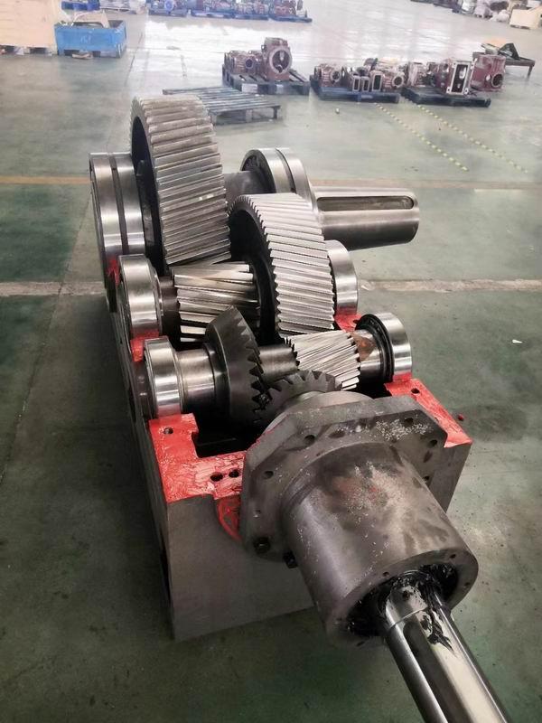
(1) Use a puller and a press to remove the gear and clean it;
(2) Measure the radial runout of the gear. The allowable range is: 0.02-0.05mm;
(3) Observe the surface wear of gear teeth and whether there are deformation, annealing, spots, peeling, etc.;
(4) Those that are severely worn and whose measurement dimensions exceed the allowable range should be replaced;
(5) When assembling a new gear, the gear hole and shaft must meet the requirements, the gear datum plane and the shaft shoulder (or the end face of the positioning sleeve) should fit, and the gear datum plane and the axis must be perpendicular;
(6) The axial misalignment of the intermeshing cylindrical gear pairs should comply with the standard. When the tooth width B ≤ 100 mm, the axial misalignment should be less than 0.05B. When B ≥ 100 mm, the axial misalignment should be less than 5 mm;
(7) The bevel gears should be installed according to the machining matching number;
Maintenance of reducer housing:
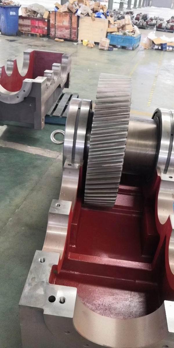
(1) First clean the inside of the casing with kerosene and observe whether there are cracks or shedding;
(2) Use a dial indicator to measure the inner hole size of the bearing assembled in the shell and record it. Generally, the ovality and conicity should be less than 0.03mm, and the inner diameter size should be less than the zero line 0-0.02mm (normal bearing outer diameter tolerance is the zero line) ;
(3) Housings that measure out of tolerance or are damaged should be repaired or replaced;
(4) All parts of the reducer should be cleaned during installation, and the assembly sequence is reverse to that of disassembly;
(5) When installing the output part, apply oil or detergent to the outer surface of the shaft. After the bearing is pressed into the shaft, the inner ring of the bearing must be close to the shaft shoulder or positioning sleeve, and the gap shall not be greater than 0.05mm;
(6) When installing the gear, the gap between the gear end face and the shaft shoulder shall not be greater than 0.1mm;
(7) The oil retaining plate should be flat and intact. After the inner ring and the shaft are set, a certain gap (2-3mm) must be maintained between the outer ring and the box;
(8) To install the intermediate shaft part, first press the bearing at the fixed end into the housing, then put the gear and intermediate spacer in order, and finally press the shaft with the bearing at the other end to align with the gear keyway below and press it into place together. Measure the end face dimensions of the assembly gland and bearing outer ring. The gap is generally: C=0.000011×(80-t)L﹢0.1 (where L is the shaft length and t is room temperature);
(9) To install the input part, first install the gland at the fixed end, press in the bearing at that end, then put the gear and spacer in order, and then press in the shaft with the bearing at the other end. Measure the size of the other end. The normal axial runout gap of the assembled gland should not be greater than 0.05-0.1mm;
(10) The gear contact spot is no less than 45% along the tooth height direction and no less than 60% along the tooth length direction. The contact is uniform and the position is close to the middle part of the tooth surface;
(11) Add new oil to the reducer. The brands must be consistent and must not be mixed. The oil level should be in the middle of the scale observation hole;
(12) Then press in the pulley, and the fixing bolt must be equipped with an anti-return pad or an anti-bolt locking plate;
(13) The joint surface of the shell must be coated with sealant, and the tightening torque of the fastening bolts
(14) When maintaining the reducer and changing the oil, drain all the old oil. The sequence of oil change intervals should be: 500 hours for the first time, 3 months for the second time, 6 months for the third time, and 12 months for the fourth time.